|
|
|

|
|
||||
|
|
||||||
|
|
|
|
Detailing The Italeri 1/35 Scale Elco PT 109 Kit
Hull - Deck - Bow Light Wiring - Foot Rail - Towing Bitt - Deck Hatch Hold Open Device - Jackstaff - Deck Vent - Life Float / Raft - Deck Cleat - Depth Charges - Grab Rails - Torpedo Tubes - Bridge - Bridge Windshield - Bridge Helmsman's Platform - Armor Plate - Searchlights - Forward Turret - .50 Cal. Flash Suppressors - Throttle Push Rod Deck Housing - Mushroom Vents - Day Room Cabin - Day Room Cabin Mast - Day Room Cabin Hatch - Day Room Cabin Window - Boat Hook, Day Room Cabin Starboard - Day Room Cabin Roof Connecting Plates - Day Room Cabin Aft Turret - Day Room Cabin And Engine Hatch Cowl Vent Assemblys - Day Room Cabin After Windshield - Heater - Rubber Boat Stowage Locker - Engine Hatch - Stern Chocks - Mufflers - |

Model by Stuart Hurley
|
|
The PT 103 class Italeri 1/35 scale PT 109, kit number 5613, is a good kit right out of the box. See David Waples initial kit review for extensive images of the kit contents. Regarding the box, don't use the cover art as any sort of reference. This page features tips for the experienced modeler that wishes to create an exceptional model of a boat in either the 103-196 or 314-367 series. On later boat designs, forward turret relocation and a 3 degree forward angle on both turrets are amongst the changes that would make a conversion more difficult. It lists factory changes made to the boats and ommisions or errors found. Most of the tips are gathered from posts at The PT Boat Forum. Links to part specific forum threads are provided. Dick Washichek has kindly allowed me to post drawings from his Elco drawing DVD. Thank you very much Dick! For best results, please purchase the DVD. It has much more detail than I can post here. Sections and menu are loosly arranged in a forward to aft direction. Not all design changes are shown. Unless otherwise noted, information found on this page applies to "factory fresh" boats. Many changes were made during their service life so to accurately model one you'll need reference images of specific boats at a specific time period. This page will be updated when I'm made aware of other changes, tips, or errors. If you notice or have any, please either post them at The PT Boat Forum or contact me at elconaut at comcast.net. All information found on this page represents a best effort on my part, please confirm for yourself if errors cannot be tolerated.
Italeri PT 109 Kit Builds
PT 109 Related Links
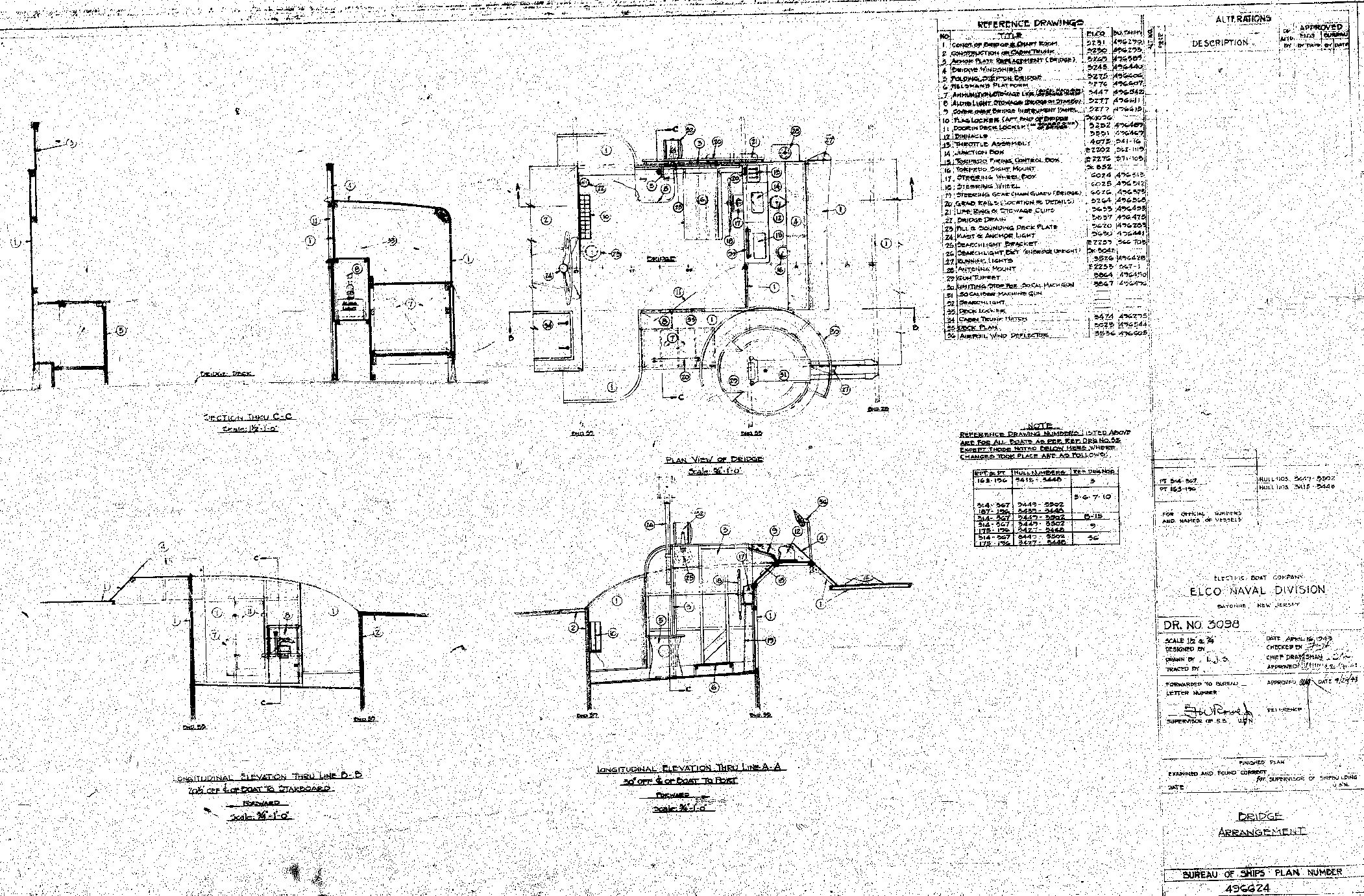
A Deck Arrangement (top view) drawing, note the many changes not shown so check reference drawings:
Updates2013 April 16, deck hatch hold open device section added. Deck Arrangement drawing added. 2013 April 15, rubber boat stowage locker (on top of the engine hatch) section added. 2013 April 13, bow light wiring, deck cleat, mushroom vent sections added. 2013 April 12, heater section added. Day room cabin section expanded. Forward cabin base cleat and forward cabin roof corner strap drawings added. 2013 April 4, bridge section expanded. Foot rail and depth charge sections added. 2013 April 1, PT 314-367 deck vent locations, stern chocks, and day room cabin after windshield added. Towing bitt / mooring bitt section expanded. 2013 March 29, dead light drawing added to day room cabin window section and muffler drawing added. 2013 March 27, intro text, day room, helmsman's platform, mast, searchlights, armor padding, starboard boat hook location on PT 109, PT 109 related links added. 2013 March 25, page added.
HullDavid Waples pointed out that the hull is flat on top, at the sheer where the deck joins. It should be a gentle "S" curve when viewed from the side, level with the water line at the bow and kicking up slightly at the stern. A PT Boat Forum post regarding these can be found here. See also the Hull page. Additional detail can be added to the hull through the addition of the many inlets and outlets found on the sides and bottom. A PT Boat Forum post regarding these can be found here. The Elco Parts Catalog Dick Washichek has made available will be of great help. DeckThe deck perimeter on the model has a raised edge, it should be sanded off. Per David Waples, the deck is flat, it should have a crown. See David's post above.
Bow Light WiringThe wiring for the bow light, see the Mast page for the deck plug.
Foot RailMany PT boats did not have depth charge release tracks on the forward deck or foot rail cutouts for them. The foot rail bottom scallops are located between frames which is why they, like the frame spacing, are different lengths. See the Hull page for frame spacings.
Link to drawing from Dick's DVD:
Towing BittPT 103-108 had a towing bitt on the forward deck, PT 109 and on had a mooring bitt. The kit includes a mooring bitt. An example of the towing bitt on PT 107 can be found here. The towing bitt was located slightly farther aft than the mooring bitt, the forward face below deck was against the aft face of bulkhead 4. The top of the towing bitt cap was about 10" above the deck at the boat center line.
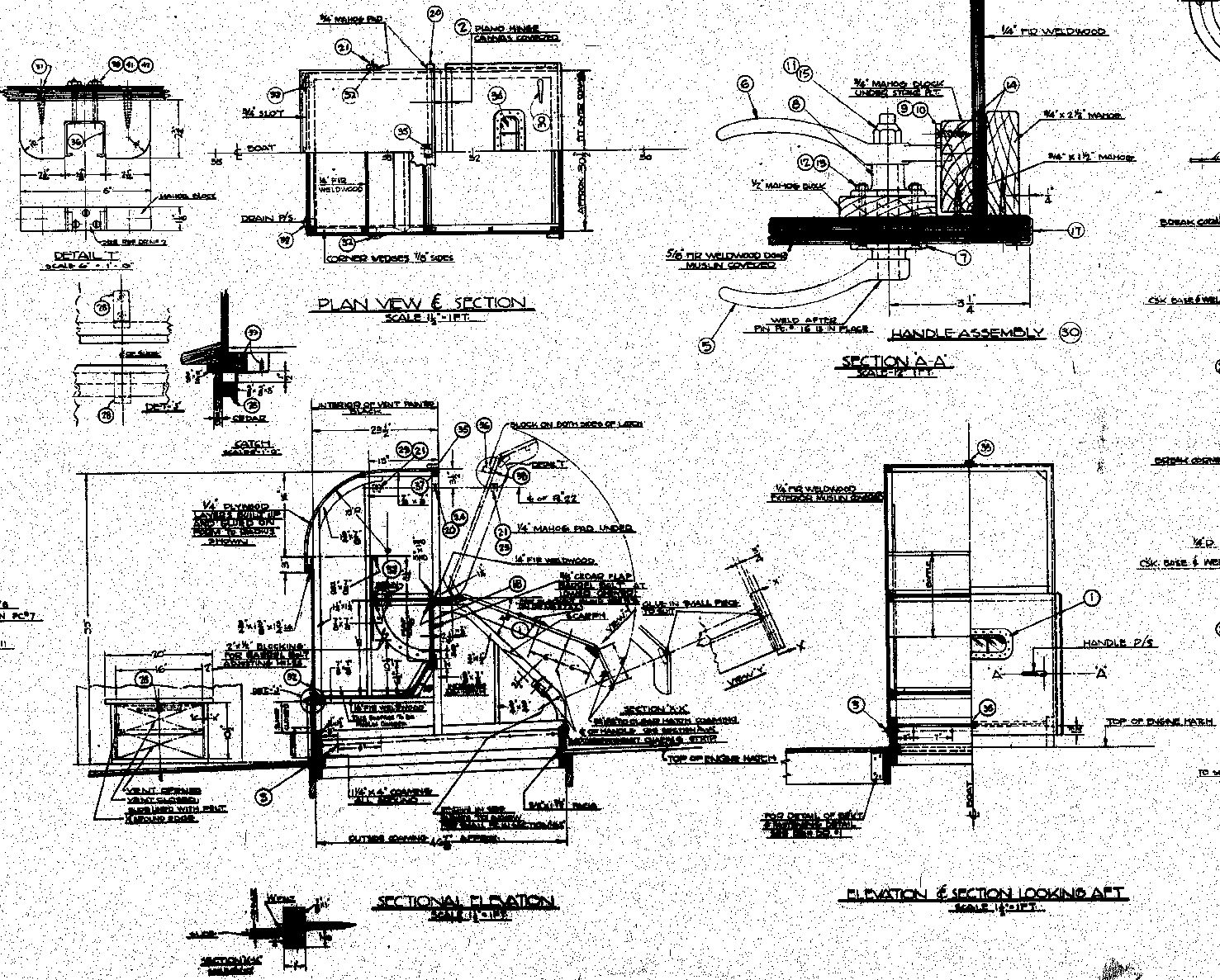
Deck Hatch Hold Open DeviceStu Hurley pointed out that images of PT 103, 105, 107, and 108 don't show these as installed. This includes images of factory fresh boats being shipped out. The devices can be seen on the Deck Hatch page. JackstaffThe jackstaff is missing from the kit. See the below image for its location, numbered 7. See the Hull page for frame spacings.
Deck VentPT 314-367 had a different style of deck vent. Deck and cabin arrangement drawings for PT 103-196 and 314-367 show the 103-196 vents. The following is a best guess for placement of deck vents on PT 314-367. They are made from scaling PT 372-383 (uses same vent as 314-367 boats) deck arrangement drawings and comparing them to cabin arrangement drawings. None of the drawings I've found give dimensional location information. I've noted any differences in the drawings. Dimensions are to the center of the round hood rings:
Port crews lavatory (foremost deck vent):
Port crews quarters:
Starboard crews quarters:
Life Float / RaftThe kit leaves this part off since the 109 had a 37mm cannon tied (scheduled to be mounted) where it normally mounts. It was possibly a Carley Float although I've never seen a PT document call it as such. Although "carley float" was sometimes used as slang for any life raft, a real Carley Float was of a unique construction, usually rectangular with half-circle ends. At its core a metal tube provided structural strength and floatation. The tube was usually covered with cork or kapok, and at least in Australia balsa wood, with an outer covering of canvas. The original 1903 patent mentions a wrap of wire cloth under the canvas. See the links below for further construction details. A common misconception is that they were of balsa construction. Although a 1998 Australian document that analyzed several of Australian manufacture found a balsa covering over a sheet iron core on one float, saying a Carley Float is made of balsa is like saying they were made of cork or kapok. Later boats with life rafts of a rectangular design were possibly made of balsa. As an aside, while researching the floats I was surprised to learn that balsa is considered a hardwood.
Further reading on Carley Floats:
I couldn't find a drawing for PTs 103-114 but an Elco drawing for PTs 115-186 & 314-367, Life Float Stowage, shows the chocks as having a 5 1/4" radius, canvas padding would make the life raft about a 5" radius. The body of the life float is about 84" x 41" on the outside. The aft edge of the life float is located 1 1/2" aft of frame 17. Drawings for PT 187-196 and Elco boats after the 367 are titled Life Raft Stowage and show what appears to be the same float.
Deck CleatNormally there were 6 per boat. Italeri only includes 4 since the 109 had depth charge tracks in place of 2 of them.
Depth ChargesAfter an incident with a torpedo hitting a depth charge on the forward deck, there is some question as to whether PT 109 had both port and starboard depth charge tracks at the time she sank. PT Boat Forum posts regarding this can be found here and here. Grab RailsPT 103-138 used a cast brass grab rail stanchion and 1" O.D. brass pipe throughout the boat. PT 139 and on used round conical teak stanchions, 1 1/2" at the base tapering to 1", with a 1 3/8" height. The grab rail was rectangular oak 1 1/4" high by 1" deep. Rail edges were well smoothed. Dick's Elco Parts Catalog gives rail lengths for both types. Torpedo TubesFrom Al Ross: "Actually, the comment about the tripping levers being incorrect is valid. The tripping levers are not the hinges attached to the breech doors. Rather, they are the devices which tripped the starting lever on the torpedo as it was ejected from the tube. On the top of the first segment of the tube forward of the breech door, you'll see two plates. The aft plate is rectangular and should have two tabs coming off each side. This is the tripping lever cover and the ELCO drawings for the MK 18 tube plus photos show this cover on the starboard side of the tube only." Bridge
Many of the changes in the series this kit covers are found on the bridge:
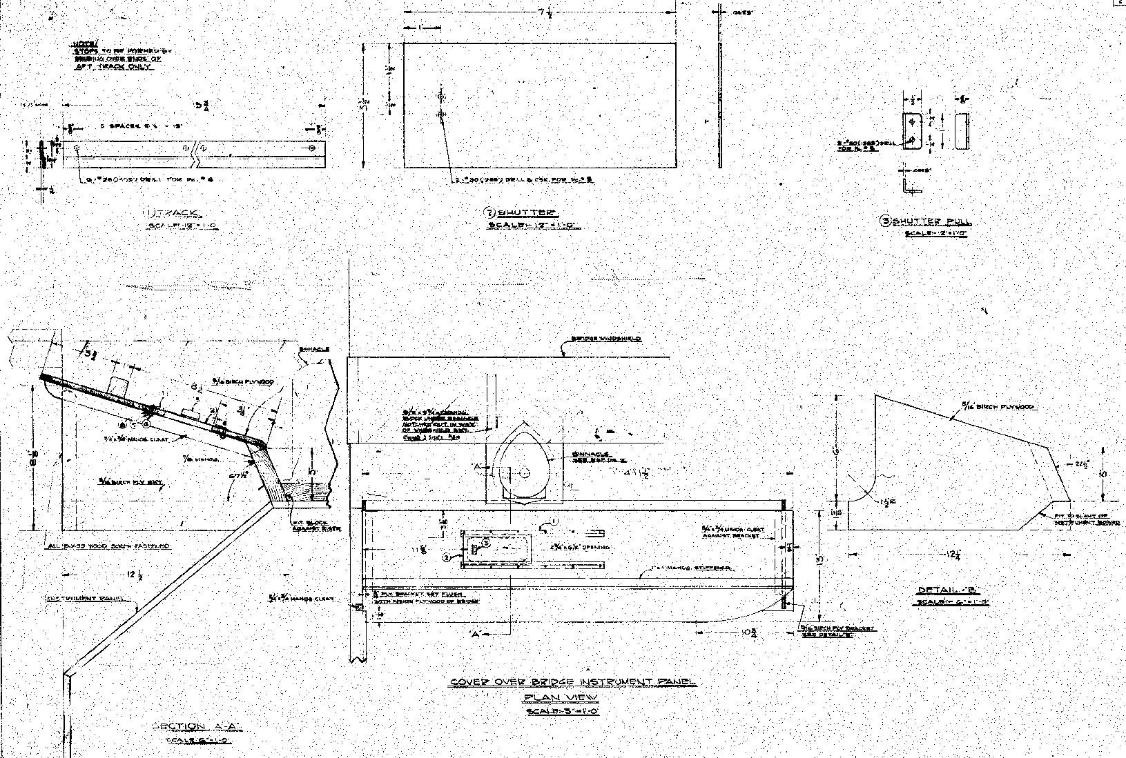
One part I haven't been able to find a drawing for is a canvas cover over the bridge control panel. The wood windshield side supports on the early boats have notches for what I'm guessing is a support bar on the aft edge of the cover. Some good views of the cover can be seen on several pages of this section of the PT King web site.
Links to drawings from Dick's DVD:
Bridge WindshieldThe only exterior framework should be the corner angles and center strip. The black seen in the image found below are rubber strips under the plexiglass. See also the Bridge And Chart House page.
Bridge Helmsman's PlatformI'm still looking into this. I did not find a drawing for PT 103-122. The deck arrangement drawing for PT 103-196 and 314-367 show what appears to be the non-skid rubber mat for PT 123-196. I'm also unsure if the rubber mat was used after armor was no longer installed. See the Helm page for PT 123-196 and 314-367. Armor PlateThe port armor plate is too short, it should extend down to the bottom of the other plates. Please see the Armor page for details. Note that of the boats this kit covers, only PT 103-150 had armor installed. PT 109 had corner padding on the armor, see the image below. I have not seen this padding on any other PT boat although this does not mean that it was unique to the 109.
SearchlightsAvailable PT 109 images show the port armor plate searchlight bracket removed. The aft armor plate searchlight stanchion was also removed leaving the brackets.
Forward TurretPT 151-162 were subject to the experimental installation of a single 20mm in the forward turret. .50 Cal. Flash SuppressorsPT 109 had the cannister style flash suppressors installed on the guns. See the .50 Cal page.
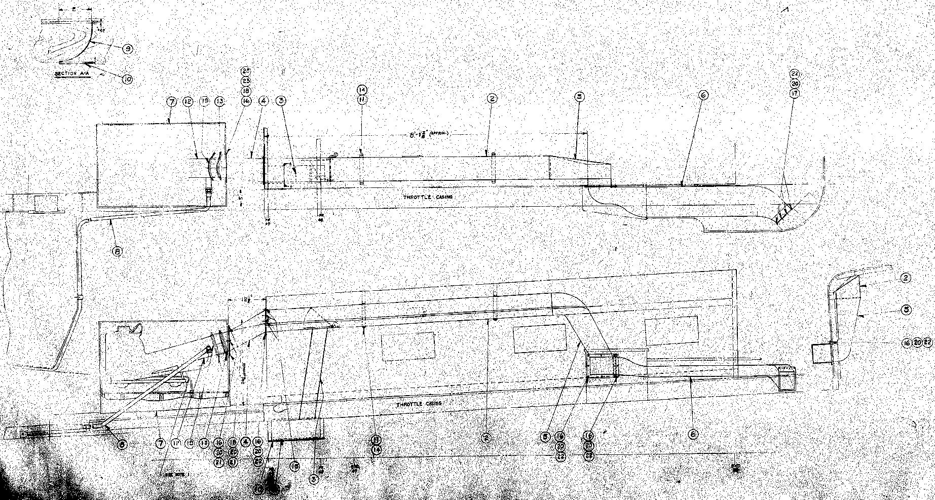
Throttle Push Rod Deck HousingThe kit has the "all low" type housing for PT 314-367, see the Throttle Push Rod Deck Housing page. Mushroom Vents4 per boat.
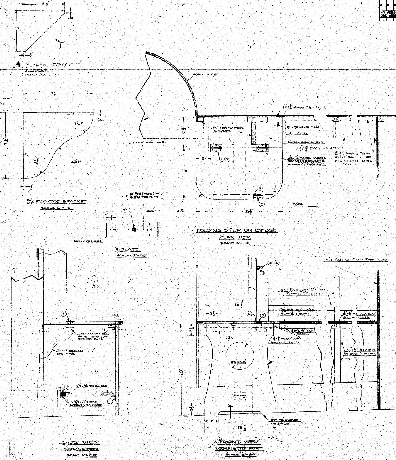
Day Room CabinThe kit has the forward and aft bulkheads (walls) at right angles to the roof. The forward and aft bulkheads should be vertical. Dick posted a day room drawing on the forum here. The facing strip should also cover the forward bulkhead roof joint. It may also be too low and small. The roof cap looks too large. The forward bulkhead window is too high. The forward bulkhead water tight door opening had 1/4" plywood doublers forward and aft. A cleat was at the forward bulkhead to deck joint between the starboard bridge wing step and the port coaming. Corner brackets were on the facing strips at the forward end. Thanks to Stu Hurley for pointing out some of these. See the images below for details.
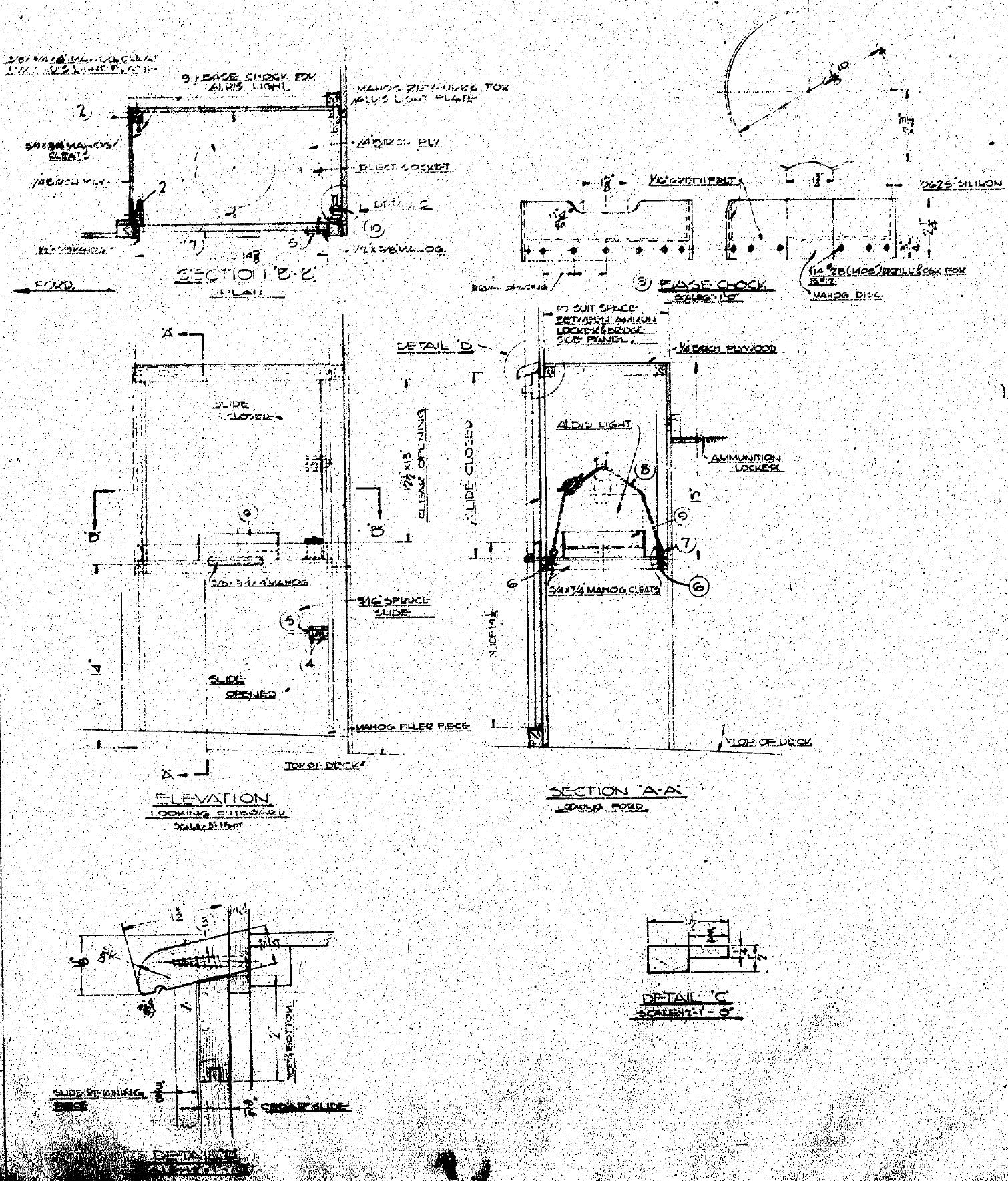
Day Room Cabin MastThis is a real nitpick. The upper eyebolts for the wire bracing are a bit too low. I mention this because the wire braces pick this detail out. See the Mast page. The flag decal should have 48 stars instead of 50. Day Room Cabin HatchThe direction that the hatch opened looks like it changed between PT 127 and PT 131. Images show that on PT 127 it was hinged on the port side and on PT 131 and on it was hinged on the aft side. Images of the hatch on PT 127 can be found here and here. If anyone has shots showing the 128-130 boats hinge direction, I'd appreciate seeing them. Day Room Cabin WindowAll the windows on the day room cabin, except for the starboard forward one, are the same as the windows on the sides of the chart house (left and right handed). The starboard forward one, under the hatch, is a fixed window aka dead light. It is the same as found on the forward end of the chart house. I'm guessing that this is because the ladder to the hatch would have prevented a window from opening. The fix would be fairly easy, sand off the drip rail, add a frame the same as on the chart house, and put the plexiglass right behind the frame (the plexiglass on the windows was set fairly deep). Frank Andruss has an image of Russ Pullano in his photobucket album that shows the dead light here. On this site, see the Bridge And Chart House page.
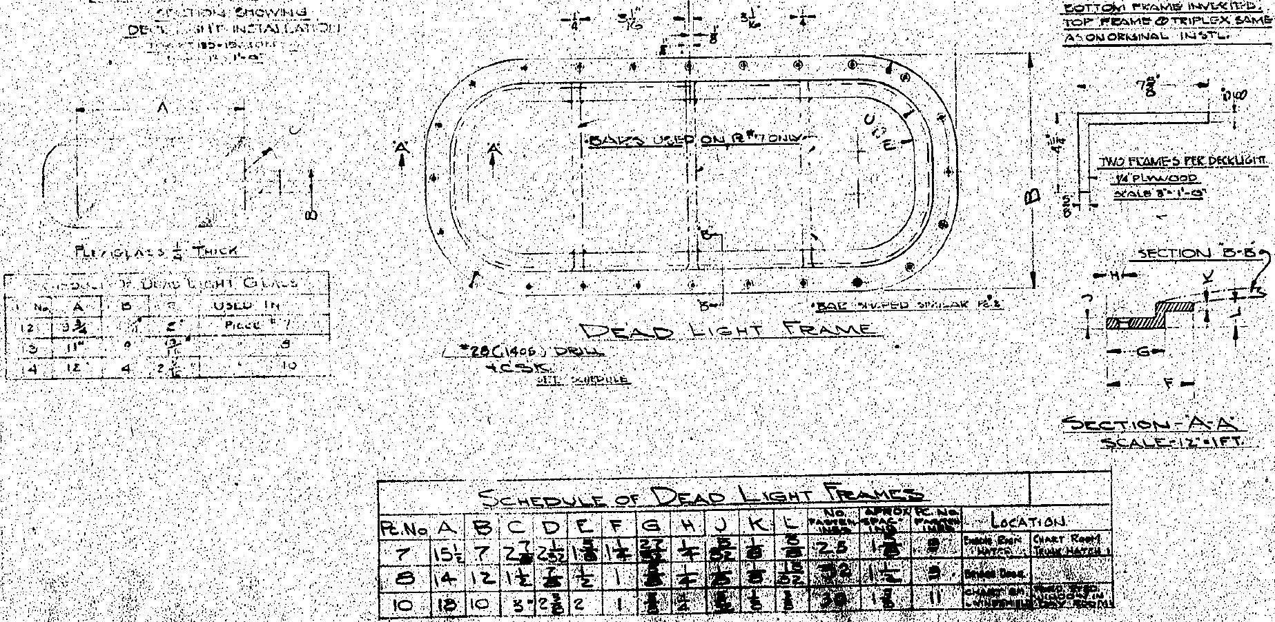
Besides the deck dead lights, there were 3 different dead lights used. The smallest was used on the engine hatch hatchway and chart house roof hatch, and was the only one with 3 bars. One type was used on the bridge door. The last was used as mentioned above. Here is a link to a drawing from Dick's DVD that shows dimensions of the dead lights:
The window on the aft end of the day room should have a drip rail above it like the others do. Boat Hook, Day Room Cabin StarboardAccording to the drawing for it (which is washed out) PT 163-196 had the starboard boat hook mounted a little lower than other boats and about 10" farther aft. The bottom of the hook bracket (the aftermost bracket) was located just above the throttle push rod cover. This will put the center of the boat hook pole about 4" above the top of the throttle push rod cover. On all other boats, the boat hook pole was 12" above the deck which placed it about 3" below the windows. The boat hook on PT 163-196 did not use the forward end socket for the pole. The drawing refers to a heater duct cover drawing but it is also washed out and I didn't find any further details. The U shaped center support clip is also moved back to about 55" forward of the aft edge of the hook bracket. The aft edge of the hook support clip is about 35" aft of the aft edge of the aftermost window. The boat hook pole itself was 10' long, including the 4" tapered end that fit inside the head. Measurements given above prefaced with "about" are my best guess made from scaling the drawing. Update to the above... Gene Kirkland has a photo of PT 109 on his site that shows the starboard location. I'll need to look into this more on other boats. Check the top photo on this page, click it for a larger image. The aft edge of the hook bracket appears very close to the aft edge of the day room cabin. Day Room Cabin Roof Connecting PlatesThese items, hard to see in photos, are missing. See the funnel photo and this page for a PT Boat Forum thread regarding these. Also check pages 2 and 3 of the forum post for drawings and photos. Day Room Cabin Aft TurretThere was some questions about the aft turret being tilted in the kit but this may be due to the bulkhead error. The aft turret top should be parallel to the base and water lines, and all sides vertical. The same with the forward turret. Day Room Cabin And Engine Hatch Cowl Vent Assemblys (PT 103-186 only)The rim around the mouths of the cowls is too pronounced, on the actual boat it is a ring of 1/2" x 1/4" half-round aluminum riveted in place. As an aside, Elco drawings name the straight vertical tube the "funnel" and the top part the "cowl", and the entire assembly a "cowl vent" or "cowl vent assembly".
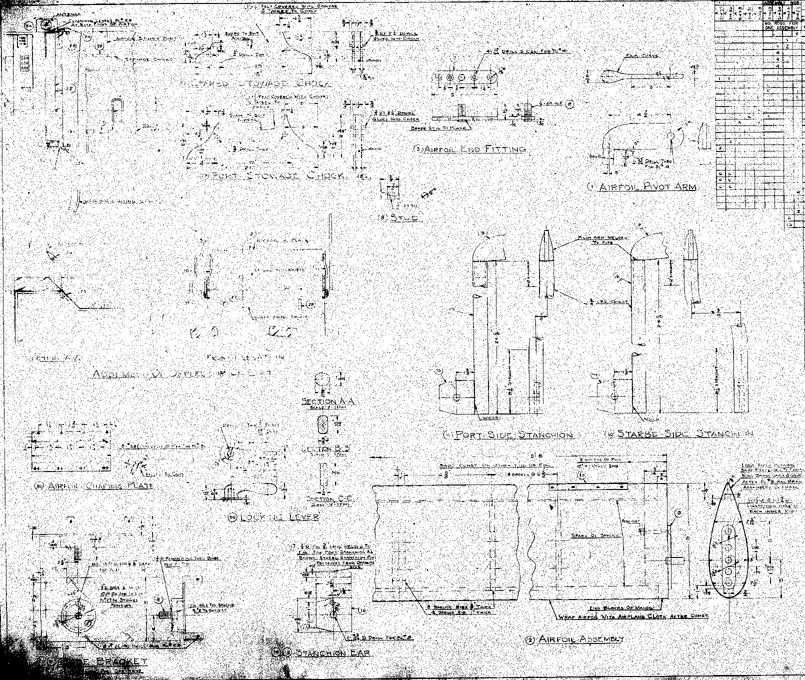
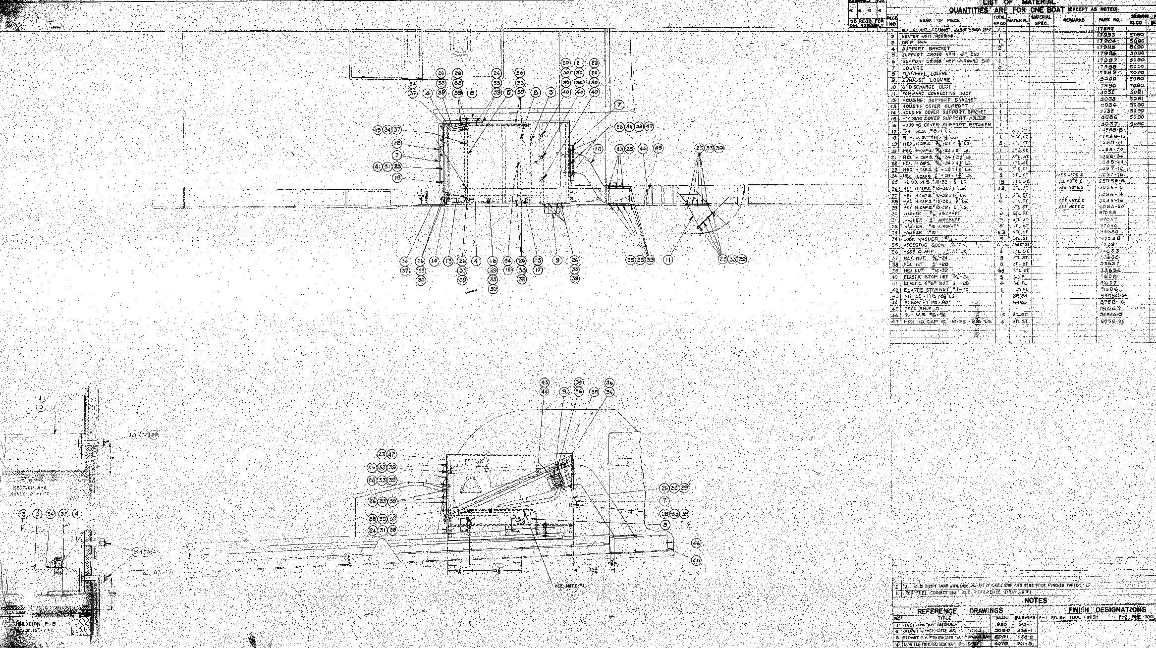
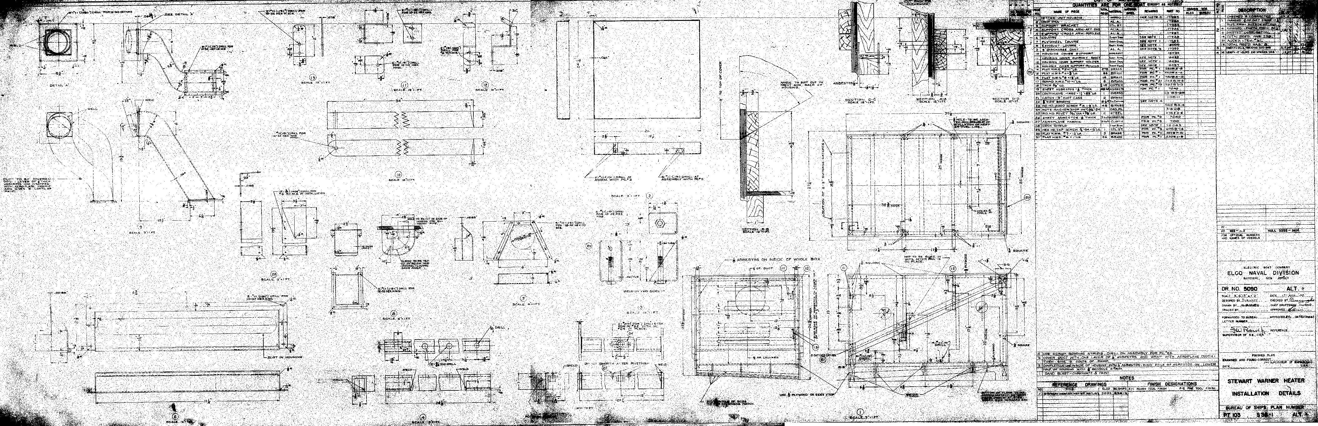
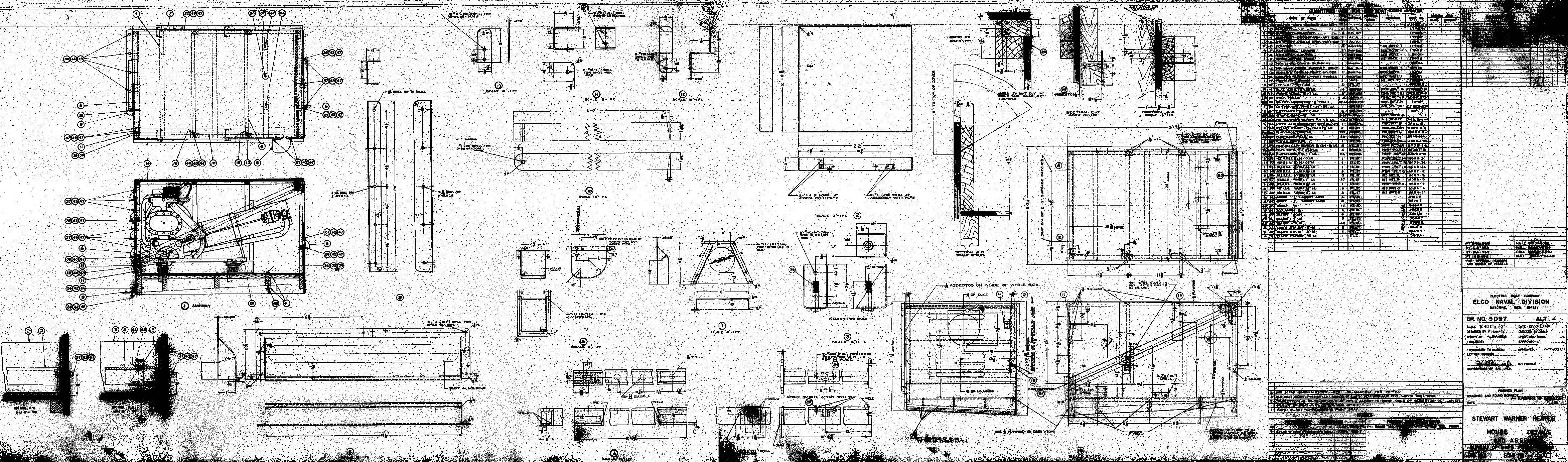
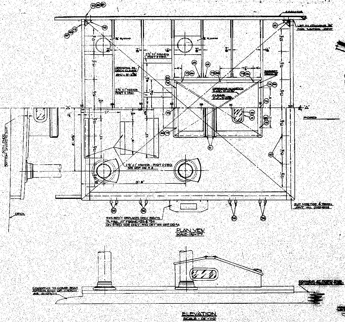
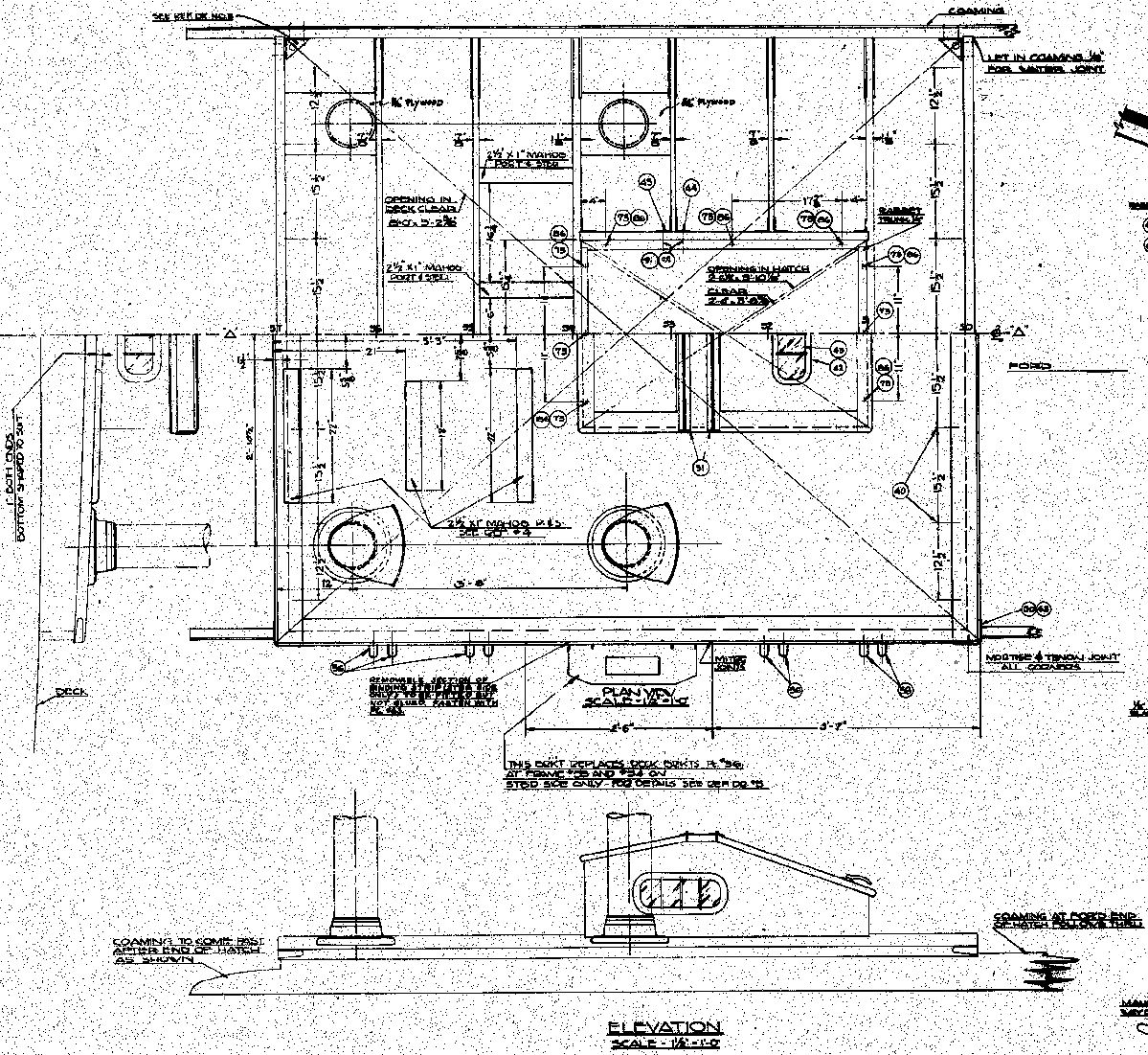
Day Room Cabin After WindshieldDeck arrangement and windshield drawings indicate that these were installed on PT 103-196 only. The starboard wing brace (round bar from starboard wing to turret) was added after (maybe) PT 115. The windshield drawing text is unclear. HeaterLocated on the starboard forward part of the engine hatch. Possibly only installed on boats headed for cold waters, some boats show a rubber boat stowage locker in place of the heater housing. See the image below for the different installations.
Links to drawings from Dick's DVD:
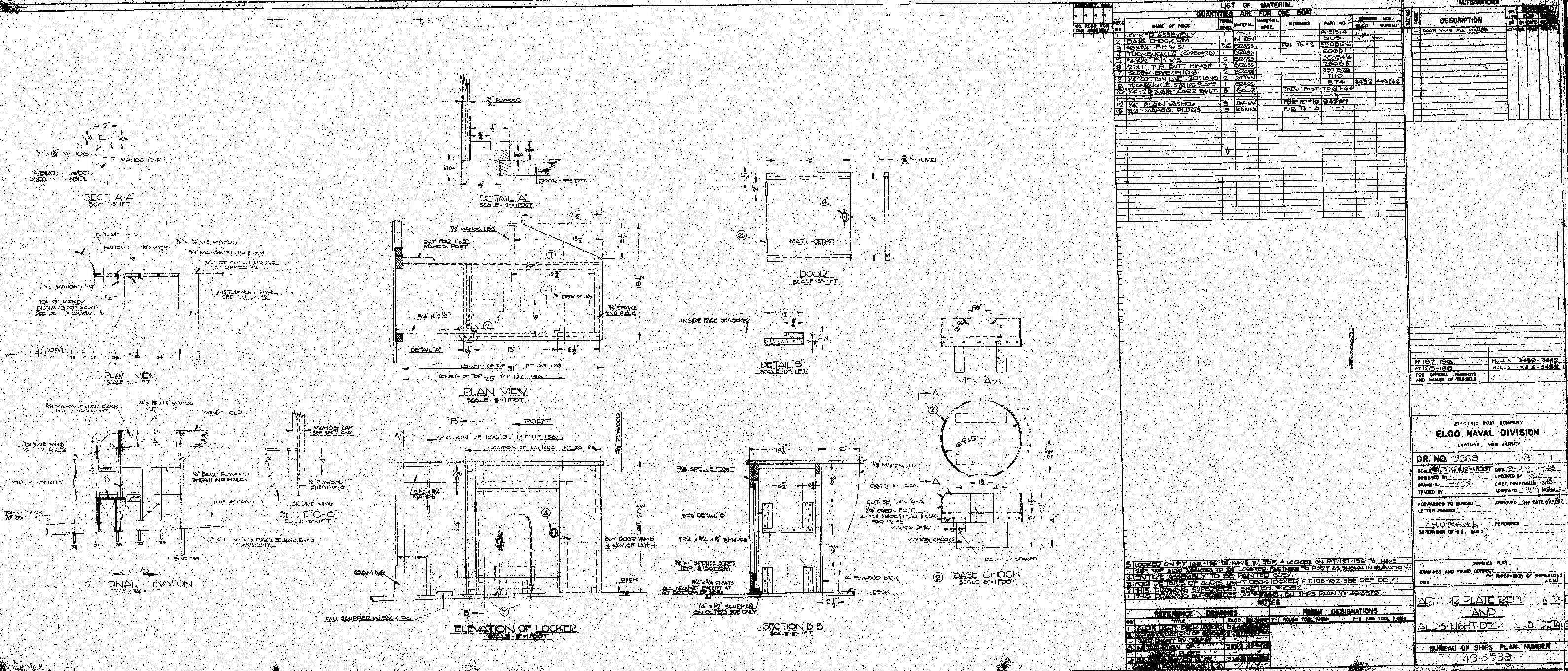
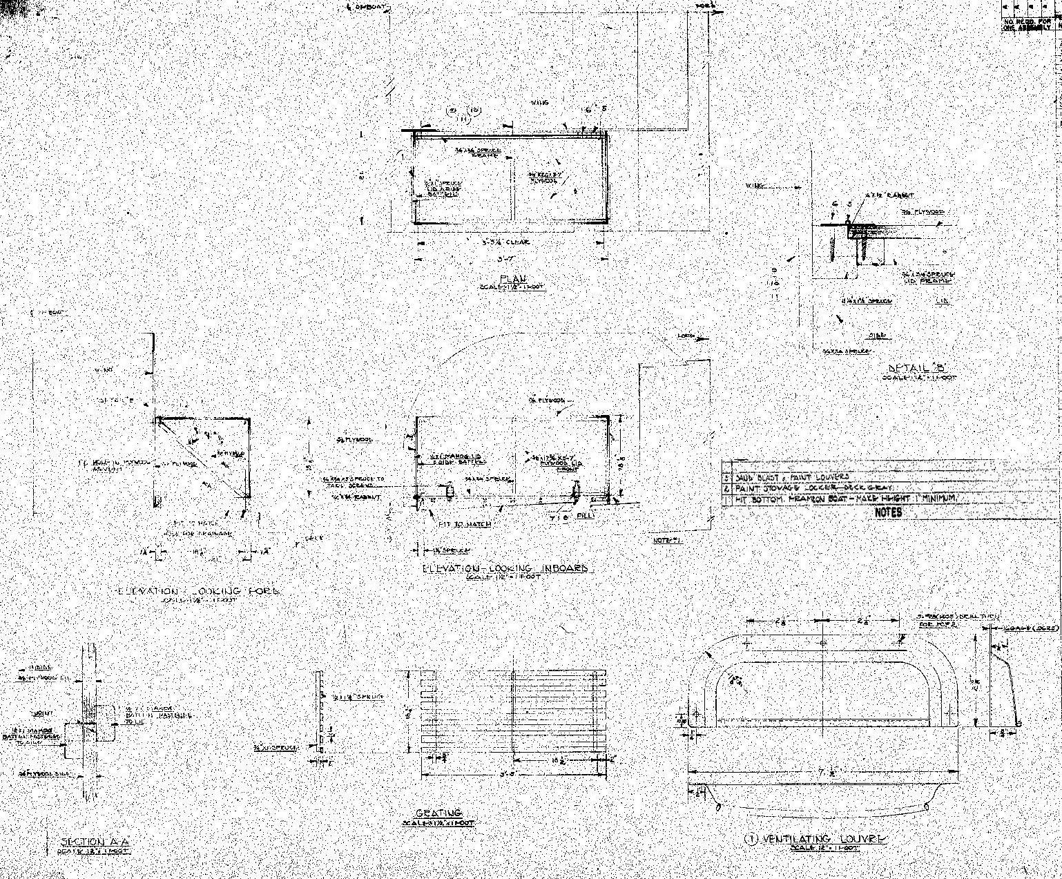
Rubber Boat Stowage LockerLocated on the starboard forward part of the engine hatch. Stu Hurley pointed these out to me on images of early boats being shipped out, thanks Stu! They must have been commonly removed, I've never seen one on images of boats in the Pacific. See the image above and check the top photo on this page to see the rubber boat stowage locker on the 109, click it for a larger image.
Link to a drawing from Dick's DVD:
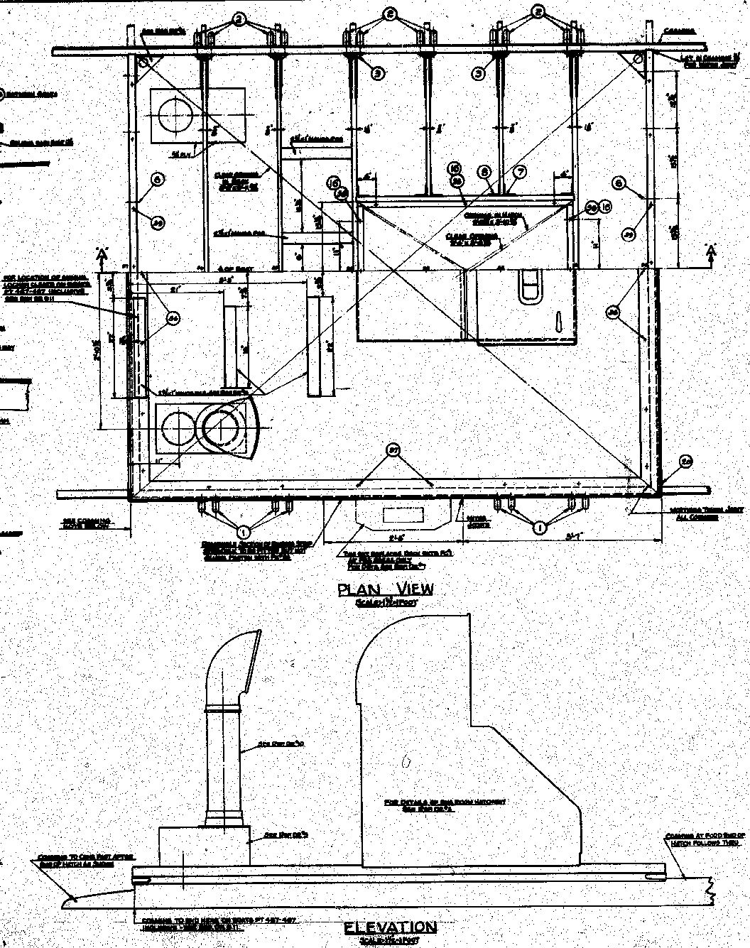
Engine Hatch
The engine hatch went through a number of changes. Links to drawings:
Stern ChocksThe stern chock drawing lists all boats except for PT 103-158. I could not find a drawing for these boats but it looks like it was of a more open design. See the image below.
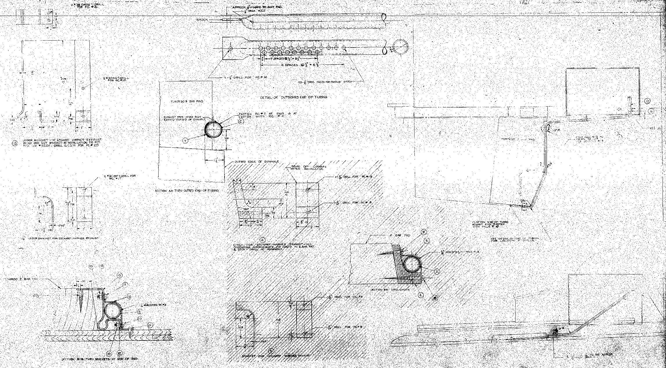
MufflersThe mufflers are missing lower mounting tabs. See Dicks Elco Parts Catalog for exhaust system drawings and images, and the image below for PT 103-145 and 147-162. See also the large 109 image link at the top of this page, the muffler stiffening bands look different from the ones on the drawing. The following dimensions are taken from Elco exhaust system drawings. Mufflers are mounted in 2 groups of 3. Muffler transom openings are 7" diameter and are spaced 15 1/2" apart in each group. The inboard muffler openings are 33" outboard of the boat center line. Height of openings on transom are 65 3/4" above boat base line. Bottom of hull at boat center line is 12 3/4" above base line at transom. See the Hull page for base line information. Mufflers angled in at the bottom 10 degrees.
|

.:|:. © copyright 2008 Jeff Davidson, pt103.com .:|:.
|


