
|
|
|

|
|
||||
|
|
||||||
|
|
|
|
USN PT Boat Elco 103 Class Day Room Cabin Trunk
|

|
|
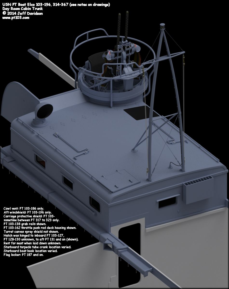
Updates 2017 March 14, added reference photos of the early mast rest, and an unknown canvas structure. 2014 March 18, updated aft, top, and starboard views to reflect an updated .50 mount. 2013 December 21, updated aft, top, and starboard views to show the rounded starboard aft corner post. 2013 December 18, updated aft view. 2013 December 16, updated top and aft views. Added image showing woods used in construction. 2013 December 5, updated rain guards over windows. All images updated. 2013 December 3, corrected the grab rail locations on all views. They were slightly too far inboard. Added a temporary aft view. 2013 November 24, corrected the supply duct layout and added the connecting duct for PT 103-162 on the forward view. 2013 November 11, corrected life ring athwartships position on the day room cabin trunk top view, and vertical position on the port and starboard views. 2013 November 7, corrected life ring athwartships position on the day room cabin trunk top view, and added the aft turret. 2013 November 1, forward view added. 2013 October 6, top view added. 2013 September 27, page added. The following images show dimensions and placement for an Elco 80' PT boat day room cabin trunk, in particular for an early 103 class. These drawings are based on measurements given in original Elco drawings. Where not available or legible for a part, it is labeled "this is a guess" or similar. Besides errors on the authors part, this drawing may contain errors due to the many modifications made to original designs, drawing quality, or the drawings may not reflect either the original design or the modified one. Please confirm dimensions given here for yourself if errors cannot be tolerated. Images are for non-commercial personal use only, please obtain permission for any other use. On PT 103-162 boats with heaters (possibly PT 139-141 only), the sections of the throttle push rod deck housing that ran alongside the day room cabin trunk (sections 2, 3, and 4) were also used as a heater duct. I don't know if the connector duct was used on non-heater equipped boats or on PT 163-196, or if cover plates were used. On non-heater equipped boats, images show a cover plate on the flange where the duct coming from the engine hatch mounted heater attached to the throttle push rod deck housing at the aft end of the cabin trunk. The aft turret usually had a canvas spray shield, see the Turrets page for some examples. Stu Hurley, author of the Italeri PT 109 Build page, let me know of a few observations he made regarding the torpedo tube cranks and mechanisms on the early 80' boats. He noticed in images of PT 103 and 105 as seen here on Gene Kirkland's PT King site that the boats did not have the long handled cranks mounted on the day room cabin trunk roof. And that the early boats may have lacked the 90 degree gearboxes as seen in an image of PT 107 here. They might have used the short cranks seen on the torpedo tube drawings. Note that images showing the tube cranking apparatus are fairly rare so it is hard to pinpoint when the change was made. Some other reference images can be found here: PT_Boat_Components_Torpedo_Tube_Images_Elco.html.
Application and details for PT 103-196 and 314-367:
Dimensional details for PT 103-196 and 314-367:
Outboard ViewsClick images for full size drawings
Woods Used In Construction
Reference ImagesThe early mast rest on PT 111. Also note the canvas buttons on the side of the windshield, and engine hatchway hatch.
Canvas structure on PT 141 utilizing the buttons mentioned above. Although not attached to the hatch, it is likely that it was when fully erected. The structure is possibly a booby hatch or air funnel to the engine compartment
The following are selected day room cabin trunk related sections from the Navy PT boat build manual found at http://archive.hnsa.org/doc/pt/specs/index.htm. Please note that this manual is a later version than the 103 class, read coverage notes below the title. Details changed even within the same series:
*****************************************
BUREAU OF SHIPS
NOTE: The Detail Specifications are based on Specifications for Motor Torpedo Boats PT 103 to 138 design No. 80-N-3 (dated 2 January 1942) and addenda thereto (dated 22 February 1943), as prepared by Electric Boat Company, Elco Naval Division, Bayonne, N. J., with the minimum modifications made by the Bureau of Ships to make the hull specifications applicable to PT 565-624 Class. Detail Specifications For Building Motor Torpedo Boats, March 1944, provides the builders specifications for PT 565-624.
*****************************************
CREW'S DAY ROOM
*****************************************
Flooring of chart house shall be of 5/8 inch fir plywood, with mahogany bearers, well fastened to longitudinal bulkhead and with headers as required. Flooring of tank compartment (day room) shall be of fir or birch plywood, and shall be completely removable for access to or unshipping of fuel tanks. There shall be one main section of flooring mid-length of the compartment, built up in box-panel form which shall include hatch to center tank, and shall have ledges across forward and after sides to support separately removable panels placed in the four corners of the room, also the raised portable steps over fuel tank connections (see Section W-1-k). The entire floor shall be carried on longitudinal sides by heavy cleat on side panels of day room, with parting strips, and designed to function as spreader for inboard supporting panels or chocks, for the wing fuel tanks. All joints shall be closely fitted, and properly landed, to obviate as far as practicable, circulation of gasoline fumes from the tank compartment.
*****************************************
Superstructure shall be of simple form, all straight sided and plumb, except the raked and angled forward end of radio house and bridge shelter. The trunk above crew's dayroom shall be built with framed-up plywood side and ends, and top only being removable, to permit unshipping fuel tanks. Any tank may be unshipped independent of the other two. Top shall be molded plastic or fabricated plywood, covered with aeroplane fabric, doped on, and is provided with means of securely bolting to sides and making watertight transverse joints. It is unnecessary to dismantle turrets in removing either engine or tank hatches. House tops shall have heat insulation of Onazote or equal to within about 8 inches of house sides.
*****************************************
All ports shall be of special type with improved drain pans and scuppers, except in crew's dayroom and chart house sides which shall be fitted with hinged metal ports with integral black-out shutters and equipped with wire mesh insect screens satisfactory to the Supervisor of Shipbuilding. Eliminate windows from forward side of chart house.
*****************************************
W-1-j.
Stowage for .50 cal. ammunition shall be provided in crew's dayroom under settee on port side, and in locker on starboard side of bridge, with outboard door, forward of the machine-gun turret. Stowage shall be provided for four boxes of ammunition.
W-1-k.
The sides and top of day room trunk shall be constructed as described in section O-1, and shall include the after port .50 cal. machine gun turret, with main and depressed firing floors, limiting stops, exit door, and adequate drainage, as per plan. ***************************************** |

.:|:. © copyright 2008 Jeff Davidson, pt103.com .:|:.
|