
|
|
|

|
|
||||
|
|
||||||
|
|
|
|
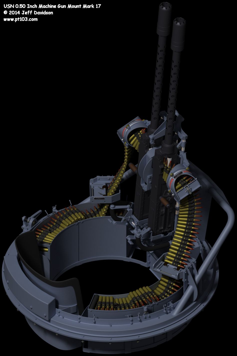
USN 0.50 Inch Machine Gun Mount Mark 17
|

|
|
Updates 2014 April 8, mount gridded and detail drawings updated. 2014 March 18, page and mount drawing updated. Also updated are the views on the day room cabin trunk page that include the mount (starboard, top, and aft views). 2009 January 23: Page added. The following image shows dimensions for an USN 0.50 Inch Mount Mark 17 as used on PT boats. These drawings are mostly a guess based on mount images and the general drawings in the March 1943 manual 0.50-Inch Machine Gun Mounts, Mark 17 Mods. 1 and 2. Please confirm dimensions given here for yourself if errors cannot be tolerated. Images are for non-commercial personal use only, please obtain permission for any other use. A special thanks to Jerry Gilmartin who took some measurements for me from an actual carriage on PT 658. Jerry also supplied Richard Pekelney of hnsa.org with the Mark 17 mount manual for scanning. Additional Mark 17 mount information, including text descriptions of the Mod. 0 hand brake and bearing train, can be found in the February 1943 Motor Torpedo Boat Manual. Also available on the hnsa site is the turret mount found on certain earlier PT boats, The Dewandre-Elco Power-Operated Machine Gun Turret. The Mark 17 mount included the Cradle, Mark 9 and Carriage, Mark 9. The cradle remained the same while the carriage went through 2 modifications by the manuals date of March 1943.
Visible carriage modifications, Mod. 1 & 2:
Visible carriage modifications, Mod. unknown but seen on early 103 class boats:
The Mark 17 mount manual includes references to the following publications, title exactness not checked:
Drawing Notes
Shown:
Not shown:
Click image for full size drawing
Exploded Views
Detail Views
Reference Images
From the movie "They Were Expendable"
Excerpts from the machine gun section of the February 1943 manual The Motor Torpedo Boat Manual regarding Mod. 0 hand brake and bearing train: Chapter 8. .50 CAL. BELL AIRCRAFT MOUNT 1. The Bell Aircraft twin cradle for .50-caliber machine guns is a flexible, lightweight, scarf-ring type mount equipped with a hydraulic system to absorb recoil shock. It is designed to be fired by either or both hands. It is manufactured in accordance with Bell Aircraft Corporation drawing 03-038-075.
Bearing Train
Hand Brake
Excerpts from the manual 0.50-Inch Machine Gun Mounts, Mark 17 Mods. 1 and 2:
ORDNANCE PAMPHLET NO. 951
1. Ordnance Pamphlet No. 951 was prepared from Bureau of Ordnance drawings, and the material furnished by the Bell Aircraft Corporation and the Electric Boat Company. 2. The 0".50 Mount, Mark 17 Mod. 1 differs from the Mark 17 in the use of a new track bearing and a new brake, as well as the addition of a horizontal stowing latch and canvas covers for the ammunition boxes. 3. The 0".50 Mount, Mark 17 Mod. 2 is the MG Mount, Mark 17 converted to include the changes incorporated in the Mark 17, Mod. 1. The Mark 17, Mod. 2 is identical to the Mark 17, Mod. 1 except for the fixed bearing race and the attachment of the outer bearing shield. This conversion affects the carriage only, which becomes Carriage Mark 9, Mod. 2, instead of Mark 9, Mod 1.
Chapter 1
1. The 0".50 Mount, Mark 17 Mod. 1 is a hand-operated machine-gun mount, carrying two caliber 0.50 Browning aircraft machine guns. This mount is also designated 0".50 Assembly No. 41, and consists of the following major subassemblies:
2. The principal features distinguishing this mount from the earlier 0".50 Mount, Mark 17 are these:
3. Operation characteristics and installation dimensions of the subject mount are identical with those of 0".50 Mount, Mark 17. The heavy brake ring has been eliminated, and the brake shoe of the new brake operates against the outside of the fixed ring. 4. The carriage of the mount provides unlimited train which is accomplished by the operator exerting pressure, in the direction desired, on a winged back rest attached to the rotating carriage. (See pl. 2.) 5. The gun cradle is supported on trunnions by a yoke which is pivoted on the support structure. This arrangement permits the guns to be manually elevated, depressed, and traversed within the limits set, irrespective of the position of the carriage in train. The maximum elevation is 85°, the maximum depression is 15°, the traverse movement, i.e., the rotation of yoke axis, is limited by stops from 10° to 15° to either side of the center line, depending on elevation of guns. Depression of guns is limited by a circular rail supported by a protective shield or by other suitable means. This depression stop prevents the guns from being pointed at the ship's personnel or structure when the gunner is firing over the boat. (See pl. 1.) The depression-limit stop rail is normally installed by the shipbuilders and shaped according to the mount location and ship's structure. 6. For information on operation and cleaning of gun, see O.P. No. 716 (War Dep't. SNL A 36).
Weights
Chapter II
1. The carriage of the mount consists of a fixed ring with a flange which is bolted down to the boat's structure, and a rotating structure which supports and carries the cradle, the ammunition-box supports, the spent cartridge and link chutes, a back rest, a counterweight, a hand brake, and the stowing and securing latches. The rotating structure of the carriage is supported on a large rotating ring and the fixed ring; the two rings compose the roller-bearing path for training the mount.
Train Bearing
Hand Brake
4. To hold the mount in train in any fixed position, turn the brake handle 180° to the right for maximum braking effect. The hand brake may also be used to apply varying degrees of braking effort by engaging the brake-handle detent in any one of the three intermediate notches provided on the cam surface of the brake bracket.
Ammunition Boxes and Cover
6. Ammunition boxes should be loaded so that the end of the first row of cartridges laid on the bottom of the ammunition box will extend up the rear end of the box with three or four cartridges hanging over the top of the rear of the box. Thus, the tail end of the belt from the front box can be connected to the front end of the belt in the rear box. 7. From the boxes the ammunition passes through lower and upper ammunition guides to the guns (see pl. 3). When the front box is empty the ammunition will feed from the rear box. Where time permits, however, the empty front box should be removed, the rear box slid forward, a full box replaced at the rear, and its belt connected to the end of the belt in the front box. CAUTION: As the aircraft gun is used on this turret, initial bursts should be limited to 75 rounds, with a desired rate of about 20 rounds per minute thereafter. Caution should be observed against possible "cook offs" of the round in the barrel chamber of a hot gun. 8. To protect the ammunition from the weather, a canvas cover is provided that fits over the open tops of two adjacently-placed ammunition boxes. A slit in the cover permits the ammunition to pass through the cover and to feed into the guns. Although initial burst can be fired with the cover in place, it is best to remove the cover as soon as feasible when firing is done. The cover is secured in place by hooking the cover grommets on four hooks, which are attached to the support ring.
Spent Cartridge and Link Chutes
Cradle-Locking Latches
Chapter III
1. The 0".50 Cradle, Mark 9 for two 0.50-caliber machine guns, absorbs recoil shock through the utilization of hydraulic shock units. It is a flexible-type cradle, designed to be fired by either or both hands. (See pl. 7.) 2. The cradle frame is made up of four parallel bearers on which are assembled front and rear trunnion slides. Four shock-unit assemblies (two for each gun) are attached at their forward ends to the rear-trunnion slides. At the rear they are attached to the cradle back-plate support. 3. Deflector assemblies are bolted to the bearers and support a yoke and chute assembly serving both guns. Bolts holding outer ends of deflector brackets to bearers also hold continuous-feed rear brackets in place. 4. The cradle back plate houses trigger and safety mechanism, including trigger-synchronizing adjusting screws. This back plate is easily removed by loosening knurled nut on bottom of cradle back-plate support, and the two knurled screws at the top of the hand grips. 5. A sight and stowage-latch support forms the front member of the frame and is designed to accommodate a standard ring sight. 6. Provision is made for mounting a bead sight in a bracket bolted to the yoke and chute assembly. Functioning of Hydraulic Shock Units 7. The purpose of the hydraulic shock unit is to reduce recoil shock produced by gunfire. This is accomplished by combining the functioning of an hydraulic piston with the reaction of a specially-designed recoil spring. 8. When firing with gun in level position, the major portion of the recoil shock is absorbed by the action of the hydraulic piston - the spring serving to return the gun to normal position after recoil. 9. Firing at a declined angle, recoil is counteracted by the hydraulic piston and weight of gun. 10. With the gun in an inclined position, the spring offsets the weight of the gun and recoil shock is absorbed by the hydraulic piston. 11. Recoil actuates piston (B1) (see pl. 8, fig. 1) compressing the special recoil spring (B2). This movement develops oil pressure behind the piston, as shown in cut, forcing valve (B3) from its seat, thus permitting oil to flow into the oil reservoir (B4) as indicated by direction of arrows. It will be noted how air ball (B5) is compressed on recoil stroke. 12. On the return stroke (see pl. 8, fig. 2) check-valve spring (B6) forces valve (B3) closed, and pressure of air in air ball (B5) on oil forces open valve (B7) opening aperture (B8) to facilitate return flow of oil as indicated by the arrows. |

.:|:. © copyright 2008 Jeff Davidson, pt103.com .:|:.
|